
VETHY / VX2000SP / PRODUCT AND APPLICATION GUIDE
VX2000SP Outdoor Unit Placement: Planning a 640 × 465 × 190 mm Vertical Package
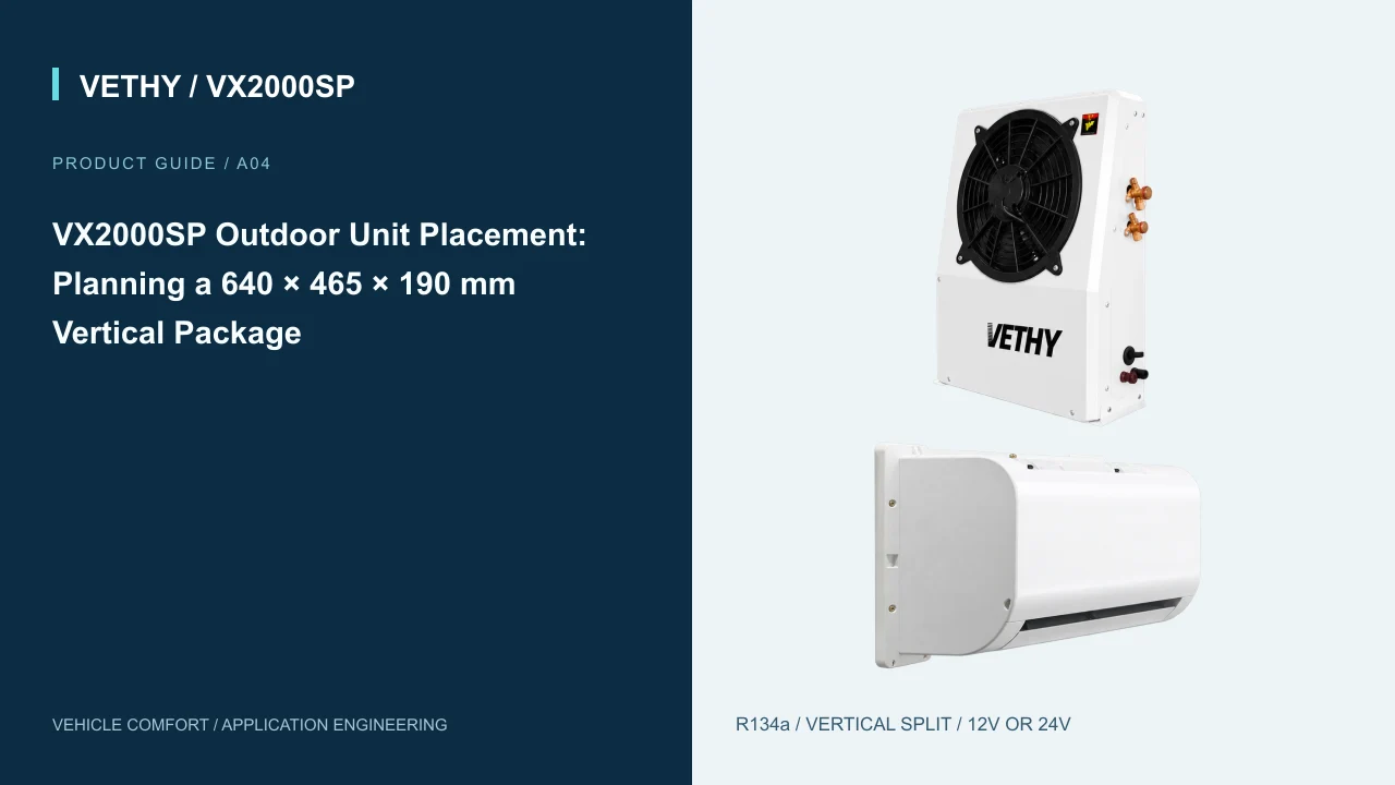
The VX2000SP outdoor unit measures 640 mm high × 465 mm wide × 190 mm deep in its published vertical layout. Plan the complete installation around that outline: mounting support, confirmed air paths, connection access, nearby moving equipment, and maintenance access. Prepare front and side photographs with measurements, coordinate the indoor position and routes, and ask VETHY and the installer to review the proposed arrangement before approving permanent vehicle modifications.
Plan the space around the unit, not only its outline
The VX2000SP outdoor unit gives buyers a clearly defined starting point: a vertical package measuring 640 mm high, 465 mm wide, and 190 mm deep. Those dimensions help a workshop identify possible locations before preparing a vehicle. They do not, by themselves, define the complete installation space. A workable position also needs a suitable mounting arrangement, an open air path, connections that can be installed and inspected, and access for future maintenance.
This makes placement a buying decision as well as an installation decision. An attractive equipment price becomes less useful if the selected location requires extensive changes to existing storage, body fittings, or service access. Recording the available space early lets VETHY and the installer discuss a specific vehicle layout instead of exchanging general statements about whether a split air conditioner will fit.
Start by drawing the proposed outdoor position on a photograph. Add the measured height, width, and depth available, then mark everything that moves nearby. Include cab movement where applicable, doors, covers, lockers, and any equipment that a technician must reach. A photograph with dimensions is much more useful than a photograph without scale.
For the complete product overview, visit the VX2000SP split parking air conditioner page. This guide focuses on turning its outdoor dimensions into a practical placement brief.
Read the vertical dimensions in the correct order
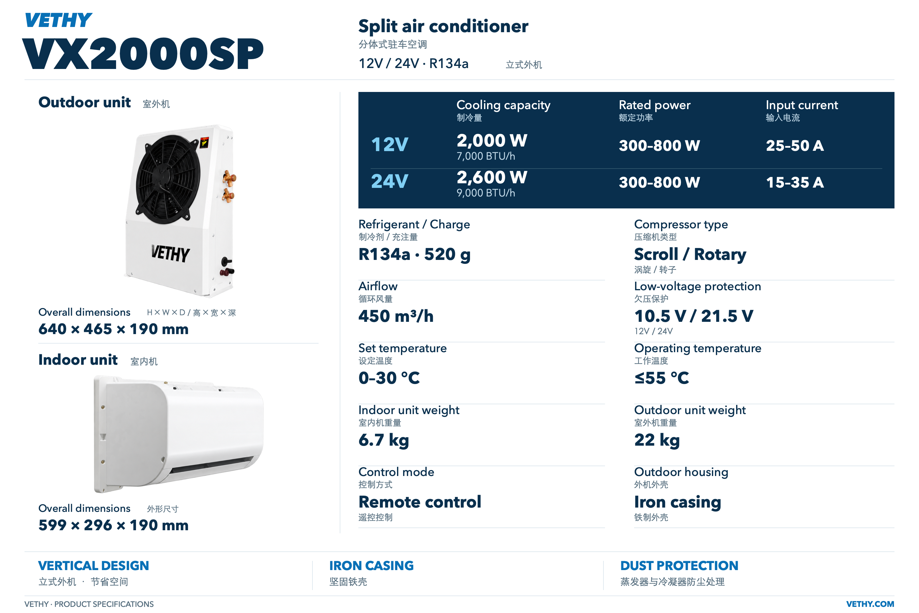
The outdoor dimensions are explicitly height × width × depth: 640 × 465 × 190 mm. Keep that order on drawings, purchase discussions, and workshop notes. A horizontal sketch using the same three numbers can lead to a different understanding of the product envelope, especially when a purchasing team and a workshop communicate through translated documents.
The vertical layout is relevant when the vehicle offers a taller mounting area. Buyers should evaluate that area in its installed context, including anything projecting into it. A wall can appear large in a straight photograph while handles, brackets, hinges, or nearby equipment reduce the usable surface. Measure the actual candidate area rather than estimating it from the overall rear wall.
The 190 mm depth describes the outdoor unit itself. It does not establish the final projection from the vehicle after brackets, connections, and other installation details are included. Ask the installer to show the final installed outline in a side view as well as a front view. That simple second drawing can reveal an obstruction that the front view hides.
Treat rotating the unit as a technical question requiring confirmation. The published vertical format should guide the initial plan; the three dimensions do not authorize another installation orientation. Buying a package that matches the available vertical area is more straightforward than making an orientation assumption after delivery.
Build a complete installation envelope
A useful installation envelope combines the product outline with the space needed to install, operate, and maintain it. VETHY's published dimensions establish the first part. The remaining parts belong in a vehicle specific plan confirmed before work begins. Avoid inserting an arbitrary clearance and presenting it as a VX2000SP requirement.
| Planning layer | What the buyer can record now | What needs confirmation |
|---|---|---|
| Product outline | Outdoor height 640 mm, width 465 mm, depth 190 mm | Correct installed orientation |
| Mounting area | Dimensions and photographs of the proposed support area | Bracket design and support suitability |
| Operating space | Nearby walls, panels, lockers, and other obstructions | Required air paths and clearances |
| Connection space | Possible routes toward the indoor unit and power supply | Connection positions and access needs |
| Maintenance space | What can be opened or removed nearby | Service access and removal procedure |
| Moving equipment | Door, cover, and cab movement where applicable | Clearance throughout the relevant movement |
This table can become the first page of a workshop brief. Give each layer an owner and record the response beside it. A buyer may own the vehicle photographs, the installer may own the proposed bracket arrangement, and VETHY may answer product connection questions.
The value is practical: unresolved items become visible before the order becomes urgent. A supplier can respond to a marked connection question more effectively than to a general request for an installation guarantee.
Compare candidate locations before choosing one
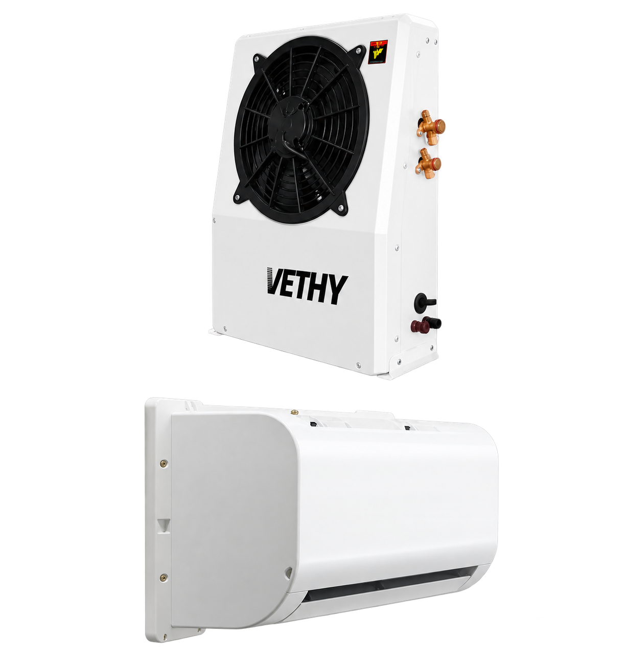
Identify more than one possible location when the vehicle layout allows it. The aim is to compare the complete installation, including daily access, rather than select the first surface large enough to hold the unit. A location with a shorter connection route may still be inconvenient if it interferes with a frequently used locker.
Use the same photographs and measurements for every candidate. Describe what is adjacent to the unit, what sits above and below it, and what changes when doors or covers open. Record whether the vehicle carries removable equipment in the same area. An empty vehicle photograph can conceal conflicts that appear during normal work.
Separate essential conditions from preferences. Access to an existing safety or service function is an essential condition. Keeping the outdoor unit visually aligned with another fitting may be a preference. Making this distinction helps teams resolve conflicts without repeatedly reopening the whole layout discussion.
The final choice should have a short written reason: the area supports the proposed arrangement, permits the confirmed air path, allows connection access, and preserves the vehicle functions identified in the brief. If a candidate remains uncertain, keep it marked as provisional. A location should become approved because its outstanding questions have been answered, not because it has appeared in several drawings.
Protect the outdoor air path in the layout
The outdoor position must allow the unit to perform its heat rejection role. Planning therefore needs to consider surrounding panels and equipment, including additions that may be fitted later. Ask VETHY and the installer to identify the relevant inlet, outlet, and clearance needs for the supplied configuration before building an enclosure or adding a decorative cover.
The published 450 m³/h airflow value should not be used to size an outdoor enclosure. It is an airflow specification for the product and does not establish condenser airflow. Treating it as an outdoor ventilation design value would introduce an unsupported assumption at a critical point in the installation.
Show possible obstructions on the layout rather than describing the location as simply open. A nearby panel can affect one part of the unit while the overall area looks unobstructed. Photographs from the side and above help the supplier understand these relationships. Include any existing shield or body recess in those photographs.
Think about the working vehicle, too. Stored items, temporary covers, or later accessories can change an initially clear area. The operating handover should identify space that needs to remain available and explain why. That makes the placement plan useful after installation, when drivers and maintenance staff make everyday decisions about storage and access.
Give the mounting plan a defined scope
The specification lists an outdoor weight of 22 kg. Preserve that wording in the installation brief: the source does not identify the weight as net, gross, or shipping weight. The indoor weight is listed separately as 6.7 kg. Neither figure replaces a mounting assessment for the actual vehicle and supplied equipment.
Ask the installer to identify the proposed support structure, bracket arrangement, fastening approach, and access needed to inspect the assembly. Record which parts come with the air conditioner and which are supplied or fabricated locally. An unspecified bracket responsibility can delay a straightforward purchase once the product reaches the workshop.
The outdoor housing is described as an iron casing. That material description helps identify the supplied package, but it is not evidence of a corrosion, vibration, impact, or weather protection certification. If the intended work environment creates a specific requirement, put that requirement into the buying discussion and request relevant evidence.
Maintenance should influence the mounting design from the start. Discuss how a technician will reach the relevant points and how the unit could be removed if necessary. A mount that is easy to fabricate can still create unnecessary service work if nearby fittings have to be dismantled for routine access. Ask for an installed view that shows both the equipment and the technician's access route.
Coordinate connections with the indoor position
The outdoor and indoor units are parts of one split system. Their positions should be developed together. Choosing the outdoor location first and leaving the indoor unit as a later detail can create awkward routes, inaccessible transitions, or conflicts with the intended resting area.
Mark a proposed connection corridor between the two positions. Show where the route passes through or around the vehicle structure, and identify covers or furnishings along it. VETHY and the installer should confirm connection details and permitted routing for the supplied configuration. Do not infer a maximum connection length from the case dimensions or product photographs.
Keep electrical supply planning in the same discussion. The VX2000SP has separate 12 V and 24 V specifications, so the order needs a confirmed voltage choice. Route and protection design should be based on the selected version and installation requirements. The published current ranges are reference fields, not a complete cable or fuse schedule.
Indoor condensate handling also needs a clear route and verification step. The outdoor dimensions alone do not answer where water from indoor cooling will go. Ask the installer to show the drainage arrangement and include a functional check during commissioning. For the comfort side of this coordinated layout, see the VX2000SP indoor placement guide.
Planning example: a compact rear wall area
This is a planning example, not an installed customer project. A buyer is considering a rear wall area that appears tall enough for the vertical outdoor package. The first photograph shows a clear wall, but a side photograph reveals an adjacent locker lid and a route used to reach other equipment.
The team first marks the 640 × 465 mm front outline and the 190 mm case depth. It then adds a separate provisional boundary for the mounting arrangement and connection area. No generic clearance is assumed. The supplier is asked to confirm the relevant air paths and access requirements against these marked views.
The installer opens the locker through its complete normal movement and photographs the result. The candidate location is revised so that daily locker access remains practical. The connection corridor is then checked against the planned indoor position, avoiding an early commitment to a mounting point that would make the internal route difficult.
Before approval, the buyer requests a final side view showing the complete installed projection. The workshop records who provides the brackets and where future inspection access will be available. The result is a reviewable placement proposal: one selected location, a coordinated route, and an explicit list of confirmations still needed.
The benefit comes from resolving conflicts while moving lines on a drawing is easy. The same method can be used on another vehicle, but the measurements and approval remain specific to that vehicle.
The buyer also assigns a decision date to the outstanding questions. If the location cannot be confirmed before that date, the team reviews the second candidate rather than shipping equipment against an unresolved drawing. This is especially useful when different people manage the vehicle, purchase, and workshop schedule. A concise status field beside each question prevents an unanswered message from being mistaken for approval. The placement record becomes a working document with a clear next action.
Planning example: an area beside existing equipment
In this second planning example, a vehicle has two possible vertical mounting areas. One is closer to the preferred indoor position; the other offers easier maintenance access. Existing equipment occupies part of the first area, and its cover must open during service.
The buyer prepares a comparison sheet with identical views for both positions. Instead of deciding only by connection distance, the team records daily access, maintenance access, possible obstructions, and any body work each option requires. The existing equipment's service movement becomes a visible requirement rather than a note remembered by one person.
VETHY is asked to review product related questions for each candidate, while the installer evaluates the support arrangement and complete route. If one candidate requires a cover around the outdoor unit, the cover remains an unresolved design item until its effect on the necessary air path has been reviewed. It is not accepted simply because the case fits inside it.
The team selects the location with the best complete arrangement and records the tradeoff. That may mean accepting a different route to preserve useful access. The exercise also creates a reusable fleet record: future vehicles can be compared against the approved arrangement, with differences flagged for review instead of assuming that a similar looking body is identical.
If another vehicle has an extra locker or a different cover, the reference drawing shows exactly what needs another look. The team can retain the confirmed parts of the arrangement while reviewing the changed area. This is more efficient than starting every discussion from an unmarked photograph, and more dependable than copying a bracket position without checking its surroundings. The reference remains useful because it records the conditions behind the original decision.
Check the finished placement against the approved plan
Installation acceptance should begin with the agreed layout. Compare the complete installed outline with the drawings, including projection, brackets, and connection access. If the workshop made a change during installation, record it and resolve any effect on product access or vehicle functions before closing the job.
Operate the adjacent doors, lids, and covers identified during planning. Check relevant vehicle service movements under the installer's procedure. A stationary photograph cannot demonstrate clearance throughout a movement. Record the result in plain terms so the next person understands what was checked and what conditions applied.
Have the installer demonstrate the access needed for inspection and maintenance. Confirm that the identified outdoor air paths remain available and that temporary installation materials have been removed. Keep any product specific maintenance directions with the handover record rather than expecting the vehicle user to reconstruct them from the layout drawing.
Then review the installation as a working area. Ask where normal tools, accessories, or personal items will be stored and whether that use could obstruct the approved space. Place an appropriate reminder in the vehicle's operating information when needed. The purpose is to preserve the conditions under which the position was accepted.
Finally, capture the actual installed arrangement in clear front and side photographs. Include a view of important connection access and retain the drawing revision used for approval. These records support future service discussions and make a repeat order easier to specify. They also create a clear boundary between the product's published dimensions and the details of this particular installation.
Keep the record available when adding other equipment later. A new storage box, cover, or accessory may change access around an otherwise satisfactory placement. Referring to the approved views helps the team check that change before fitting it. The initial planning work continues to provide value throughout the vehicle's working life.
Turn the agreed location into a purchasing brief
Send the approved photographs and drawings with the quotation request. State the model, voltage version, proposed outdoor position, indoor position, and intended use. A workshop preparing equipment for a parked resting period needs a different information set from a distributor ordering stock without a specific vehicle.
Give the brief a revision date and one named contact for each decision. If an updated photograph changes the proposed position, replace the earlier drawing in the shared package and explain what changed. A single current package helps avoid a supplier quoting against one layout while the workshop prepares another. For repeat orders, include the vehicle or body reference used internally so the equipment can be matched to the intended installation record when it arrives.
Ask the quotation to identify the supplied components and installation responsibilities. Include mounting hardware, connections, controls, and any locally provided items in the scope discussion without assuming that each is included. Record the answers beside the drawings so the purchasing and installation teams work from the same version.
The final handover should show the installed location, connection route, and access points. Keep the model and voltage identification with those records. Photograph the finished arrangement from the same angles used in the planning brief; matching views make deviations easier to assess.
For a fleet purchase, use the first completed installation as a documented reference and review subsequent vehicle differences. A repeated model name does not establish identical body layouts. The VX2000SP guide hub connects this placement decision with electrical planning, comfort, maintenance, and configuration topics. Send VETHY a marked vehicle layout to turn a general product enquiry into a focused fitment discussion.
Frequently asked placement questions
What are the VX2000SP outdoor unit dimensions?
The published outdoor dimensions are 640 mm high × 465 mm wide × 190 mm deep. They describe the vertical outdoor package. The completed installation also needs a confirmed mounting arrangement, connection access, operating space, and maintenance access. Ask for a drawing showing the final installed outline before approving the location.
Does a wall larger than the unit guarantee that it fits?
It establishes only that the case outline may fit in that view. Check adjacent equipment, moving covers, the complete projection, air paths, and the route to the indoor unit. Use photographs and measurements of the actual vehicle, then have the proposed arrangement reviewed before committing to modifications.
Can I use 450 m³/h to design an outdoor enclosure?
No. The published airflow figure does not establish condenser airflow or provide an outdoor enclosure design requirement. Send the enclosure proposal and surrounding dimensions to VETHY for configuration specific review. Keep the required outdoor air paths visible in the final approved plan.
Is the 22 kg outdoor weight a shipping weight?
The source labels it as outdoor weight without establishing shipping, gross, or net scope. Use the published description accurately and request the relevant transport or mounting information for your decision. The separately listed indoor weight is 6.7 kg; it should remain a separate field.
What should I send VETHY before ordering?
Send the model, selected voltage, measured candidate area, front and side photographs, nearby moving equipment, proposed indoor position, and intended connection route. Identify any special environment or mounting requirement. This gives the supplier and installer a concrete basis for clarifying suitability and quotation scope.
Product sources
- VETHY VX2000SP verified product specifications — VETHY.
- VETHY VX2000SP bilingual specification sheet — VETHY.

VETHY product recommendation and application analysis. Specification references identify the selected model and voltage. Installation examples are planning examples; measured project results are identified explicitly when available.
Discuss your VX2000SP application
Send your vehicle, supply voltage, occupied space, parking schedule and installation photographs for a model-specific recommendation.
Prepare your vehicle brief ↗