
VETHY / VX2000SP / PRODUCT AND APPLICATION GUIDE
VX2000SP 12V Power Planning: Build a Useful Cooling and Recharge Schedule
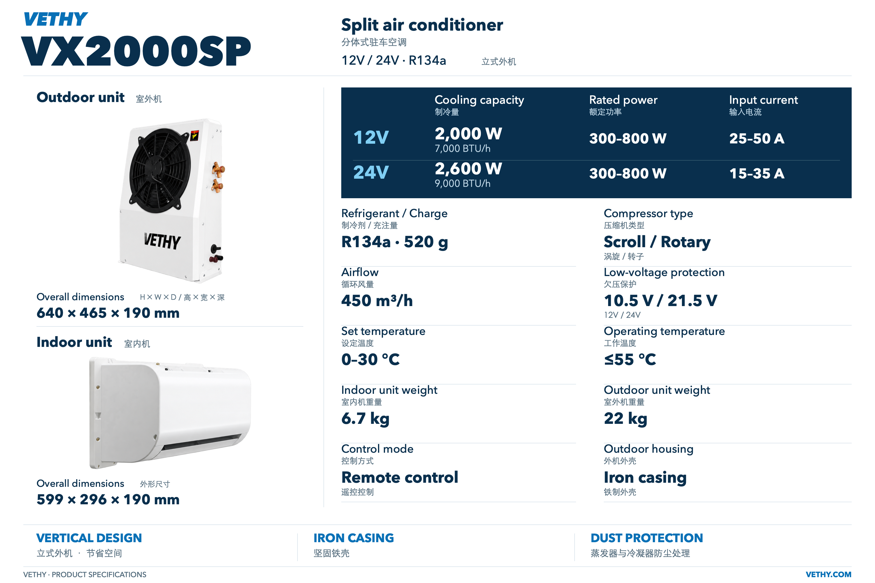
Plan VX2000SP 12V use by balancing the intended cooling schedule, the battery system’s approved usable energy, other loads, and the next recharge opportunity. The published references are 2000W cooling, 300–800W rated power, and 25–50A input current; these are separate fields rather than matched test points. Build a time block energy budget using labeled assumptions, preserve an agreed reserve, and update the schedule with observations from the completed installation.
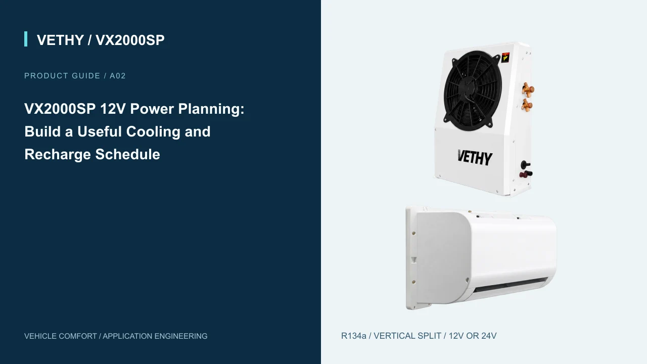
A useful 12V parking air conditioner plan connects three things: the cooling period the driver wants, the battery energy allocated to that period, and the opportunity to put energy back before the next stop. Looking only at battery capacity leaves the recharge question unanswered. Looking only at a product's cooling rating leaves both questions unanswered.
For the VETHY VX2000SP 12V version, the published references are 2000W cooling capacity, 300–800W rated power, and 25–50A input current. This guide explains how to use those separate fields alongside a practical operating schedule. Its numerical scenarios are clearly labeled planning examples. They demonstrate budgeting methods and do not represent measured VX2000SP runtime or an approved battery combination.
Keep the VX2000SP product specifications beside the vehicle information, and use the VX2000SP guide hub for related installation decisions.
1. Start with the parking schedule the driver actually needs
Write down the intended cooling periods before choosing a battery. Identify when the driver is inside, how long each stop lasts, and when the vehicle next has a reliable recharge opportunity. A single long rest and several loading waits can have similar total occupied time while placing different demands on the charging routine.
Use a normal working week as the first reference. Record the earliest stop, the longest expected wait, repeated door openings, and any period when cooling would overlap with other electrical equipment. Include a difficult but credible workday so the plan does not depend on the most convenient schedule.
Turn this information into a service objective. For example: support the occupied waiting periods between the morning departure and the afternoon recharge window, while preserving an agreed reserve. The supplier can review this objective alongside the vehicle and electrical details.
Separate essential cooling time from optional use. If a delivery schedule changes, the driver needs to know which period takes priority. A written priority rule is more helpful than discovering the energy limit after a long unplanned wait.
Finally, identify who controls charging. If charging depends on a depot routine, assign a person or process that confirms connection. The best battery plan still needs a dependable daily action behind it.
2. Understand the three different electrical and cooling references
The VX2000SP 12V specification gives a cooling capacity of 2000W, also shown as 7000 BTU/h. That describes the published cooling output reference. The rated power field of 300–800W concerns electrical input. Input current is separately listed at 25–50A.
These figures are useful for identifying the selected version and starting a supplier discussion. The sheet does not pair them into a set of common test points. Therefore, multiplying one end of a current range by a nominal voltage and comparing it with one end of the power range does not create a validated operating condition.
For energy planning, the needed quantity is electrical energy over time. A planning assumption of 500W maintained for two hours represents 1000Wh, or 1kWh. This is ordinary budget arithmetic. It does not establish that the VX2000SP will consume 500W for those two hours in the buyer's cab.
A useful working sheet keeps published references and planning assumptions in separate columns. Mark assumed average power as provisional until installation observations support it. Record the conditions of those observations so the number retains its meaning.
This separation helps purchasing, installation, and operations discuss the same project without turning a convenient estimate into a product promise. It also makes the budget easier to update when the actual route or cooling period changes.
3. Ask for usable battery energy, then define a reserve
A battery label is the beginning of the storage discussion. The proposed installation needs an agreed amount of energy available for cooling and other permitted loads under the intended operating conditions. Obtain that usable allowance from the battery system supplier or responsible electrical specialist.
Keep the allowance distinct from any energy you want to retain. That reserve may support other equipment, accommodate an unexpected wait, or reflect the vehicle's operating policy. If engine starting depends on the same electrical arrangement, have that requirement assessed explicitly within the battery and vehicle design.
For a clear worksheet, use three entries: usable energy allocated to the planned period, energy held back as reserve, and energy available to spend. Express all three in watt hours or kilowatt hours. Avoid comparing an energy figure in one place with an amp hour figure elsewhere without the required battery voltage basis.
The VX2000SP 12V low voltage protection reference is 10.5V. That threshold is a product protection reference rather than a substitute for the battery supplier's operating limits or a starting reserve policy. Define the driver's stopping rule through the approved electrical arrangement.
Give the driver a clear way to see the agreed condition. A reliable indicator and a simple instruction help translate the electrical design into daily behavior, especially when several people share the vehicle.
4. Build a time block cooling budget
Divide the occupied parking period into blocks that reflect how the vehicle is used. The beginning of a stop may involve a different planning assumption from a later settled period. Use separate rows so that changing one assumption does not require rebuilding the whole schedule.
The following is an illustrative four hour budget. The power values are selected assumptions within the published power range, not observed demand or a forecast for a particular cab.
| Planning block | Duration | Assumed average input | Calculated energy |
|---|---|---|---|
| Initial occupied period | 0.5h | 700W | 0.350kWh |
| Main occupied period | 2.5h | 450W | 1.125kWh |
| Final occupied period | 1.0h | 350W | 0.350kWh |
| Cooling budget total | 4.0h | Different by block | 1.825kWh |
Suppose the planner also assigns 0.175kWh to other permitted loads. The total planned use becomes 2.000kWh. If the approved usable allocation is 2.400kWh, the worksheet retains 0.400kWh for the agreed reserve.
Every figure after the product references belongs to this scenario. A buyer should replace it with the proposed installation's usable allowance and relevant operating observations.
The table has an immediate practical benefit: it shows where the budget is sensitive. If the main occupied period extends by an hour, that change can be entered directly. If the initial period uses more energy than expected, the operator can revise that block instead of hiding the difference in an unexplained daily total.
Test one less favorable assumption before approving the schedule. In this example, changing only the main block from 450W to an assumed 600W adds 0.375kWh across its two and a half hours. Total planned use including the other loads rises to 2.375kWh, leaving only 0.025kWh from the illustrative 2.400kWh allocation. That change nearly consumes the original reserve. The calculation does not predict demand; it shows why the buyer should examine sensitivity and preserve a deliberate buffer instead of approving a schedule that works only at one chosen average.
5. Treat the initial cabin condition as an operating input
A cab that has been standing in direct sun presents a different starting condition from one that has recently been occupied and cooled. For planning, record the state at the beginning of the stop. Useful notes include parking exposure, initial cabin condition, closed or open curtains, and the number of door openings during occupied use.
The purpose is to understand the cooling task. No single note predicts energy use by itself, but a consistent record lets the buyer compare similar workdays. An energy observation without its starting conditions can be misleading when reused for another season or route.
Review practical heat management with the driver. Where appropriate for the vehicle, parking choices, shading measures, and limiting unnecessary door opening can reduce the amount of heat that must be handled during the stop. Evaluate these measures in the actual work routine rather than attaching a percentage saving to them.
Indoor airflow also belongs in this review. The VX2000SP lists 450m³/h airflow, while its installed air path depends on placement and obstructions. Check whether bags, bedding, curtains, or stored equipment interfere with the intended discharge or return route.
If a recorded stop feels uncomfortable, first document the conditions and inspect the installation against the approved layout. That provides a useful starting point for the supplier instead of immediately attributing the result to battery capacity or changing equipment.
6. Include the small loads that share the parking period
A cooling budget becomes incomplete when it quietly excludes everything else. List the electrical equipment that will operate during the same period, such as lighting, communications devices, or other installed accessories. Use ratings or measurements relevant to the specific equipment, then record whether each item is continuous or occasional.
Keep the list short enough to maintain. A practical worksheet might group essential vehicle accessories, driver convenience loads, and occasional equipment, with a named owner for confirming each allowance. The point is to account for energy that otherwise appears as an unexplained difference.
Where a monitor reports total battery discharge, make clear that its number includes every connected load within that measurement boundary. It may not represent the air conditioner's consumption alone. If a dedicated equipment measurement is available through the approved installation, record its scope alongside the total.
Do not spend the same reserve twice. If the battery plan retains an allowance for an unexpected wait, avoid also treating that allowance as routine capacity for accessories. Give optional equipment a clear priority rule when the vehicle has limited energy available.
A short load inventory also helps future maintenance. When a new accessory is added, the operator can see that the existing parking and recharge plan needs review.
7. Calculate recharge from energy actually restored
Recharge planning should answer a specific question: how much energy can the approved charging arrangement restore before the next cooling period? Identify the source, the time available, and the information the installer can provide about energy reaching the storage system.
The most useful planning figure is net restored energy over the relevant window. A charger's nominal output alone may not describe the whole result, because vehicle loads, control behavior, and battery acceptance can affect what is stored. Ask the electrical specialist how the chosen arrangement should be assessed.
For illustration, suppose the approved arrangement restores energy at a hypothetical average net rate of 300W during the available window. Replacing a 2.000kWh planned discharge would mathematically require about 6.67 hours at that unchanged rate. At a hypothetical average net rate of 500W, the same energy amount corresponds to four hours. These are arithmetic examples, not charging promises.
Now compare the calculation with the workday. A four hour window at the first assumed rate restores 1.200kWh, leaving a planned daily shortfall of 0.800kWh against the 2.000kWh use. A larger battery can store more energy, but it does not remove that repeating recharge gap.
Resolve the gap through the approved system design or operating schedule. Options for review include a longer charging window, a different approved charging arrangement, or a shorter cooling allocation. Check the revised plan over consecutive workdays.
8. Planning scenario: one long occupied stop
Consider an illustrative vehicle that has a single long afternoon stop followed by a dependable charging opportunity. The buyer wants a clear cooling allocation and a predictable end of day routine. Start with the time block table, then replace the provisional inputs with project specific observations after installation.
Before the pilot, define what will be recorded: the initial energy indication, cooling start and finish, observed energy change within the agreed measurement boundary, major accessory use, and charging start and finish. The driver can collect a short record without becoming the electrical technician.
Review several representative stops rather than choosing the most favorable one. Compare the driver experience with the energy record. If a stop is cut short, record whether the reason was schedule change, an operator decision, an energy limit, or an equipment interruption.
The next morning, check whether charging restored the planned starting condition. This closes the loop between cooling use and recharge. A satisfactory afternoon alone does not establish a sustainable daily routine.
After review, revise the operating instruction in plain language: the intended starting condition, normal cooling period, permitted auxiliary loads, reserve indication, and charging action. Keep the supporting calculations in the vehicle file. The driver needs the decision rule, while the installer and fleet manager need the reasoning behind it.
9. Planning scenario: several short stops across a route
For an illustrative multi stop route, create one row per occupied stop. Suppose the planner assigns three half hour waits an assumed average of 600W, giving 0.900kWh in total. Two additional one hour waits at an assumed 400W add 0.800kWh. The modeled cooling total is therefore 1.700kWh before other loads.
The arithmetic is simple; the operating question is whether reliable recharge occurs between those stops. Record each charging window and the relevant net energy restored. The worksheet should follow the sequence of the day, because a later recharge opportunity cannot supply energy to an earlier stop.
Add a running balance to the worksheet. Begin with the approved starting allowance, subtract each stop's planned use, and add each verified or deliberately assumed recharge amount. Keep the reserve visible throughout the sequence. This makes the most demanding point in the route easier to find.
If one loading wait regularly extends, identify how the driver should respond before the reserve is reached. The response might involve a revised stop allocation or an agreed recharge action, depending on the approved system.
When the route changes, update the sequence. Keeping the old daily total while moving the recharge window can conceal a new constraint even if the total planned cooling time remains the same.
10. Use a small pilot record to improve the assumptions
The goal of a pilot record is a better operating plan. Choose a format the driver can complete reliably, such as one line per occupied stop with a short conditions note. Assign someone to review the records and speak with the installer when the results need explanation.
Record the model version and vehicle identifier at the top. Keep starting conditions, time, energy observations, and driver experience in separate fields. If a meter value represents the whole battery system, label it accordingly. Where data are missing, leave the entry open rather than filling it with an estimate that looks measured.
Compare observations with the planned blocks. Ask whether the stop lasted longer, accessory use changed, the starting condition was more demanding, or a charging window was missed. These are operationally different issues and can require different responses.
Bring unexpected electrical behavior to the responsible installer with the actual readings and conditions. Avoid changing protection settings or electrical components simply to make a worksheet look successful. Any design change should return through the approved installation process.
After a useful set of records, update the assumptions and date the worksheet. Keep the earlier version so that the reason for the change remains clear. This is especially helpful when another driver or vehicle later adopts the same routine.
11. Make the electrical installation support the daily routine
The intended schedule should reach the installer before the installation is finalized. It informs the review of battery allocation, charging arrangements, isolation, protection, monitoring, and driver access. Ask the installer to identify which parts of the project are included and which depend on a battery or vehicle specialist.
Published current ranges do not determine conductor or fuse sizes by themselves. The selected equipment requirements, route length, supply conditions, connections, and applicable installation design all belong in that decision. Request the completed electrical arrangement as part of the handover record.
Agree where the driver sees the relevant energy indication and how the charging connection is confirmed. If the routine requires opening a difficult compartment at every stop, test that action with the person who will perform it. Practical access can determine whether the charging plan is followed consistently.
During handover, have the installer explain the normal operating sequence and the response to a low energy indication. Keep contact and fault reporting information with the vehicle documents.
The complete installation buyer guide covers mounting, routing, and acceptance alongside electrical planning. The battery reserve guide develops the distinction between the product threshold and the reserve policy for the installed vehicle.
12. Frequently asked questions
How long will VX2000SP run from a 12V battery?
There is no single runtime established by the supplied product sheet. A useful estimate needs the approved usable battery energy, electrical demand over the intended stop, other loads, and the retained reserve. Start with a labeled planning worksheet, then improve it with observations from the installed system. Keep measured results tied to the conditions under which they were collected.
Can I use the 2000W cooling figure in the battery calculation?
Use electrical input energy for the battery budget. The 2000W figure is the published cooling capacity reference for the 12V version. The product sheet separately lists rated power at 300–800W and input current at 25–50A. Ask the supplier and installer for information relevant to the ordered configuration, and distinguish it from the average power assumptions used in a scenario.
Does low voltage protection preserve enough energy to start the engine?
The listed 10.5V reference does not establish an engine starting reserve. Battery arrangement, condition, operating limits, and vehicle starting needs require their own assessment. Have the responsible electrical specialist define the reserve policy and the indication the driver should use. Include that instruction in handover so it remains clear during an unexpected long stop.
Will a larger battery solve a daily recharge shortfall?
It can change the available storage, subject to approval of the installation. A repeated daily energy shortfall still requires an energy balance solution. Compare the energy used with what the approved arrangement restores before the next stop. Review charging time, the charging arrangement, and the allocated cooling period together instead of relying on storage capacity alone.
What should I send VETHY before discussing a 12V power plan?
Send the selected vehicle details, proposed supply arrangement, intended cooling periods, other loads, available recharge windows, and any usable energy information confirmed by the battery supplier. Include mounting photographs if installation is part of the quotation. This gives VETHY and the installer a common project brief and makes outstanding electrical questions easier to assign to the right party.
Product sources
- VETHY VX2000SP verified product specifications — VETHY.
- VETHY VX2000SP bilingual specification sheet — VETHY.

VETHY product recommendation and application analysis. Specification references identify the selected model and voltage. Installation examples are planning examples; measured project results are identified explicitly when available.
Discuss your VX2000SP application
Send your vehicle, supply voltage, occupied space, parking schedule and installation photographs for a model-specific recommendation.
Prepare your vehicle brief ↗