
VETHY / VX2000SP / PRODUCT AND APPLICATION GUIDE
Specifying VX2000SP for a 24V Truck Fleet
A VX2000SP 24V fleet specification should identify the 2600W cooling version, define vehicle installation groups, and control the mounting, electrical arrangement, supplied components, and acceptance documents. Start with a representative pilot, close its issues in a revised installation package, and release similar vehicles against that package. Keep exceptions separate and retain configuration and service records for every vehicle so purchasing, installers, drivers, and support teams work from the same approved information.
A fleet specification should make the next installation more predictable than the first. For a parking air conditioner, that means controlling the electrical version, the mounting arrangement, the supplied components, and the acceptance record for each vehicle group. Ordering several units under one model name is only the equipment part of that task.
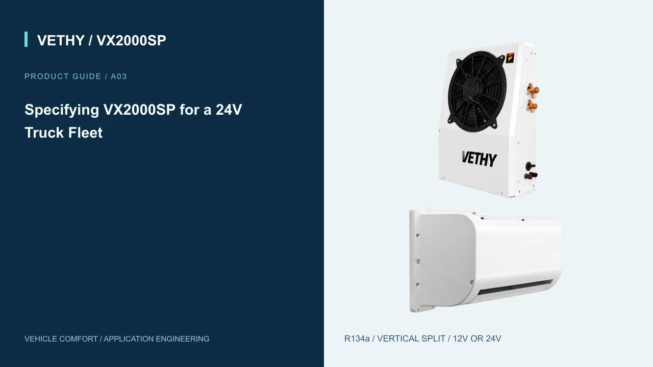
The VETHY VX2000SP 24V version is a split parking air conditioner with a vertical outdoor unit. Its published cooling capacity is 2600W, also shown as 9000 BTU/h. This guide explains how a fleet buyer can turn the product references into a clear request for quotation, a useful pilot installation, and a repeatable rollout package.
Use the VX2000SP product page as the equipment reference and the VX2000SP guide hub to connect the fleet brief with installation and maintenance topics. The fleet scenarios in this article are planning examples, not reported customer projects.
1. Define the fleet outcome in operating terms
Start with the work the fleet wants to support. Identify whether the intended cooling periods occur during loading waits, breaks between assignments, or occupied rest periods. Record the expected duration, normal occupancy, other electrical loads, and recharge opportunities. An operating description helps engineering, purchasing, and drivers evaluate the same requirement.
Choose the first vehicle group deliberately. A fleet may share a badge or purchasing category while containing different cab layouts, rear equipment, battery arrangements, and service access needs. Select a group whose installation can be reviewed and repeated with limited variation.
Give the project a small set of acceptance objectives. Examples include a documented mounting arrangement, usable airflow at the occupied position, a defined energy reserve policy, accessible cleaning points, and completed driver handover. These objectives are observable and can be assigned to responsible people.
Keep equipment approval separate from rollout approval. The product may be selected for evaluation while the installation package still requires review. Record which stage has been completed so that a quotation, a pilot order, and a fleet release are not confused.
Assign an owner for the technical specification and another for operational feedback if these roles sit in different teams. Purchasing should know whose approval is required when a supplier proposes changing a component, mounting detail, or configuration during the project.
2. Put the published 24V references into one controlled table
A controlled equipment table prevents the 12V and 24V versions from being mixed in quotations or internal records. Use the model name and voltage together wherever the ordered configuration is identified.
| VX2000SP 24V reference | Published value | Fleet specification use |
|---|---|---|
| Cooling capacity | 2600W / 9000 BTU/h | Identify selected version |
| Rated power | 300–800W | Electrical review reference |
| Input current | 15–35A | Electrical review reference |
| Low voltage protection | 21.5V | Product protection reference |
| Airflow | 450m³/h | Indoor layout discussion |
| Refrigerant and charge | R134a, 520g | Supplier installation procedure |
| Outdoor dimensions | 640H × 465W × 190D mm | Initial mounting envelope |
| Indoor dimensions | 599 × 296 × 190mm, source order | Confirm drawing orientation |
Attach the current public specification record and the bilingual product sheet to the project file. Date the fleet's approved equipment table and identify the person responsible for updating it.
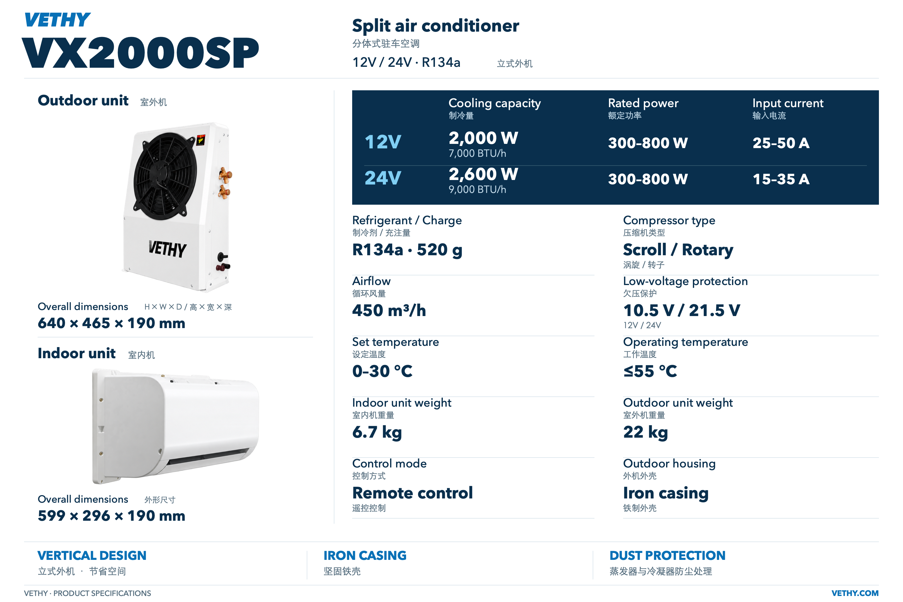
The listed power, current, and capacity fields are separate references without paired test points. Use them to start the review, then request the installation information required for the exact ordered configuration. Avoid adding efficiency figures or electrical component sizes to the controlled table unless they have their own confirmed engineering basis.
3. Divide the fleet into installation groups
Build a vehicle register with one row per vehicle and a practical installation group. Useful grouping fields include cab structure, intended outdoor location, indoor trim arrangement, battery and charging architecture, and existing rear equipment. These are the features that can change installation work even when the vehicle model description looks similar.
For each group, collect photographs from consistent viewpoints. Show the proposed outdoor position, the occupied cab, the intended indoor location, relevant electrical compartments, and nearby service points. Include measurements in the images or an accompanying sketch.
Identify exceptions early. A vehicle with an added storage box, altered cab trim, or different auxiliary battery arrangement may need its own review. Put it in an exception list rather than forcing it into the nearest standard package.
The result should be a group record that an installer can use before the vehicle arrives. It should explain the approved design, the checks still required on the actual vehicle, and the changes that trigger further approval.
This grouping also improves quotation quality. Suppliers can price a repeatable installation package for the standard group and identify the assessment work for exceptions. The fleet then has a clearer picture of both equipment quantity and installation variation before scheduling downtime.
4. Approve an installation drawing with service access
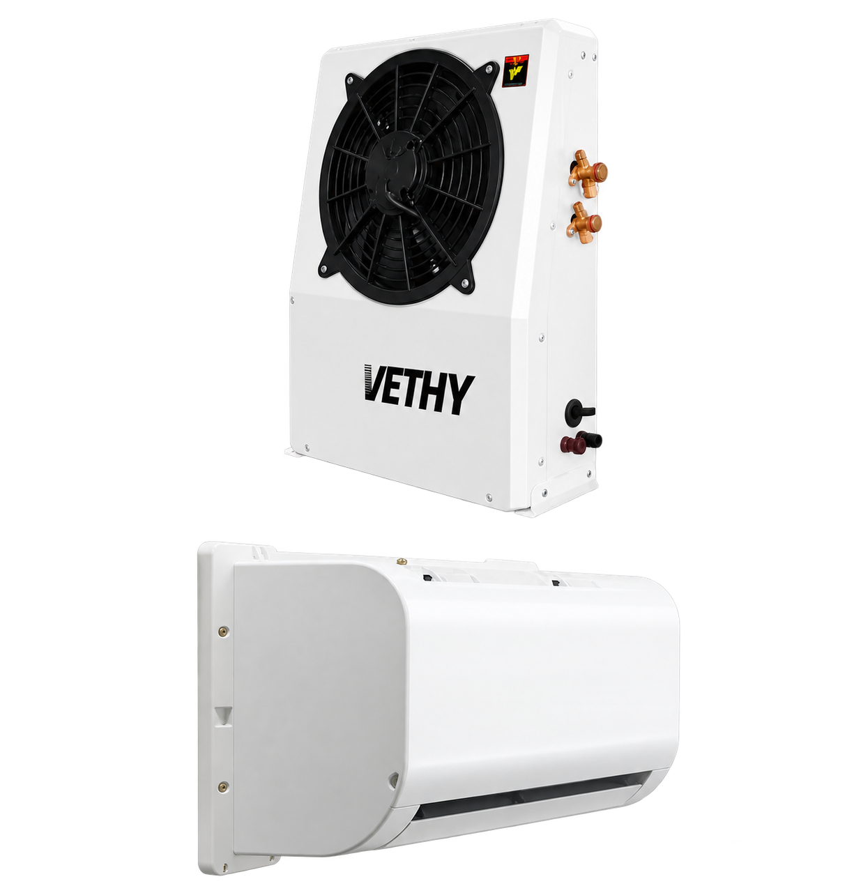
The vertical outdoor body is 640mm high, 465mm wide, and 190mm deep. Use that envelope to begin the drawing, then add the required mounting, connection, airflow, and service spaces confirmed by the supplier. Approving only the body outline leaves important parts of the job unresolved.
The drawing should show attachment points, nearby equipment, vehicle movement, and access to existing maintenance items. If the cab tilts or another assembly moves near the unit, review the relevant positions with the responsible installer. The same check should cover pipe and cable movement.
Indoor placement needs a separate view. Mark the occupied position, discharge path, return path, and the access needed for cleaning. Use photographs with normal cab equipment in place. An installation that looks open in an empty cab may become obstructed when the vehicle returns to work.
The source lists indoor weight at 6.7kg and outdoor weight at 22kg without establishing net, gross, or package scope. Keep those labels separate and obtain the weight information required for structural and handling assessments.
Approve the drawing with a revision identifier. Retain photographs before covers are installed, including routes and connections. A later installer should be able to understand the hidden work as well as the finished appearance. The complete installation guide develops this review in more detail.
5. Give electrical approval its own owner and record
Confirm that the selected installation uses the VX2000SP 24V version and identify the actual supply arrangement on each vehicle group. Record which battery system supplies parked cooling, which loads share it, and how charging occurs during the fleet's normal duty cycle.
Have the responsible electrical specialist define conductor selection, protection, isolation, connections, and monitoring for the installation. The published 15–35A current field does not determine these choices by itself. Route length, equipment requirements, supply conditions, and the approved design belong in the assessment.
Set a fleet energy reserve policy with the vehicle and battery requirements in mind. The listed 21.5V low voltage protection reference does not establish a starting reserve or a battery state of charge. The driver needs a clear operating indication and a defined response when the agreed reserve is approached.
Record electrical approval separately from mechanical completion. A vehicle can have the units securely mounted while its connection or charging arrangement still needs verification. The release checklist should make that distinction visible.
For repeat installations, provide the approved electrical arrangement and identify which checks must be repeated on every vehicle. A standard design reduces variation, while vehicle inspection confirms whether that design has been applied correctly to the actual unit being returned to service.
6. Translate cab cooling needs into an evaluation plan
The 2600W cooling figure identifies the published 24V output reference. Fleet suitability still depends on the occupied area and operating environment. Record cab layout, glass exposure, insulation information when available, occupancy, door opening pattern, and the condition at the beginning of a parked cooling period.
Define the pilot observation before installation. Agree where conditions will be recorded, when observations will be taken, and what the driver will report. Use the same process across pilot vehicles so the results can be compared meaningfully.
The VX2000SP lists a temperature setting range of 0–30°C and an operating temperature reference of ≤55°C. These are specification fields: the setting range is not a guaranteed cab temperature, and the upper reference is not a capacity rating at that condition. Review the actual duty environment with VETHY.
Use driver experience alongside the installation record. If comfort is unsatisfactory, inspect airflow, starting conditions, door use, and the approved electrical supply before deciding what should change. A useful evaluation should identify the cause of a problem rather than merely score the driver's impression.
Keep the acceptance objective specific enough to review. “Suitable for our fleet” becomes actionable when attached to a named vehicle group, a defined occupied period, and recorded operating conditions.
7. Control the supply package and configuration changes
Request a component list with the quotation. Identify the indoor and outdoor equipment, remote control, mounting provisions, connection materials, installation documents, and any items the installer must source separately. The fleet should know which parts belong to the equipment order and which belong to the local installation package.
The sheet identifies R134a and a 520g refrigerant charge. Ask for the required installation procedure and the supplied configuration details so that the installer understands the connection and commissioning requirements. Record the approved route and component choices in the installation package.
The compressor label reads “Scroll / Rotary.” If compressor configuration affects spare parts or internal procurement criteria, obtain written identification for the ordered equipment. Use that confirmation in the controlled parts record rather than expanding the label into an assumed technology description.
Establish a change process before the first volume order. The supplier or installer should identify a proposed substitution, explain its effect on the approved package, and obtain the designated technical decision. Purchasing needs enough information to preserve traceability when order details change.
Where documentation or a particular approval is required by the buyer's project, request the applicable evidence for the exact supplied equipment. Keep outstanding requirements visible in the purchase record until they are resolved, with the responsible party and next action identified.

8. Make the pilot acceptance record useful for rollout
A pilot installation should produce a reusable package. Inspect the mounting, connections, routing, drainage, access, and finished cab arrangement against the approved drawing. Record the supplied model and voltage identification before the vehicle returns to work.
Use an acceptance sheet with results and actions. Each item should have a responsible person and a place for observations, rather than only an unchecked box. If a connection is concealed, retain a photograph showing it before the cover is fitted.
Complete functional observations using the supplier's procedure and the fleet's agreed evaluation plan. Record the operating conditions and measurement scope. If a reading represents the entire battery system, label it accordingly so it is not later presented as equipment only consumption.
Have the driver demonstrate the normal control sequence, reserve response, and charging routine. The handover should also show inspection points and explain how to report a problem. Remote control is listed for VX2000SP; include remote storage and identification in the vehicle routine.
Close each pilot issue explicitly. A revised bracket detail should become a new drawing revision. A routing problem should produce a corrected route record. A driver instruction change should reach the people using the next vehicle. Rollout approval should refer to the corrected package so that the pilot's lessons travel with the order.
9. Planning scenario: twelve similar trucks and one pilot
Consider an illustrative fleet preparing twelve similar trucks for occupied loading waits. Ten have the same rear layout, while two carry additional equipment near the proposed outdoor position. The buyer creates a standard group for the ten vehicles and an exception group for the remaining two.
The first pilot is chosen from the standard group. Before fitting it, the fleet approves a drawing, an electrical arrangement, the supply package, and the observation sheet. The pilot then checks whether those documents describe a practical installation and usable operating routine.
Suppose the review identifies a service access improvement: a connection is reachable, but a technician must remove unrelated trim to inspect it. The installer revises the routing detail and records the new method before the package is released. This example describes a planning decision, not an actual VX2000SP test result.
The remaining standard vehicles are scheduled using the corrected package, with per vehicle inspection still required. The two exceptions receive separate layout reviews rather than being fitted automatically under the standard drawing.
Purchasing can now distinguish three quantities: the pilot equipment already evaluated, the standard installations ready for release, and the exceptions awaiting approval. That distinction supports realistic scheduling and prevents an open technical issue from disappearing inside a single fleet order total.
10. Build a maintenance and spare parts record around the installation
A service plan should identify the equipment, the installation package revision, and the inspection access for each vehicle. Keep unit identification and the exact supplied configuration with the vehicle record so that support requests can be matched to the correct equipment.
The VX2000SP lists dust protection treatment for the evaporator and condenser. Ask for cleaning and inspection instructions suited to the fleet's actual environment. Assign who performs the checks and where the result is recorded. A visible action owner makes the maintenance plan more dependable than a general instruction to keep equipment clean.
The outdoor housing is listed as iron casing. Include inspection of visible condition and mounting hardware in the service discussion, following the supplier and installer's instructions. The material label alone does not establish an environmental protection rating.
Ask VETHY which replacement items and diagnostic information should be identified for the ordered configuration. Separate parts the fleet is prepared to handle from work requiring the appropriate specialist. A spare part list is most useful when linked to a clear diagnosis and replacement responsibility.
Record recurring issues by vehicle group and installation revision. If several vehicles report a similar symptom, the fleet can check for a shared route, bracket, accessory change, or operating condition. The dust and airflow maintenance guide supports this service conversation.
11. Ask for a quotation with technical and commercial boundaries
Send the same fleet brief to each bidder. Include the vehicle groups, voltage requirement, quantities by stage, installation locations, drawings or survey information, operating objective, and required documentation. Ask the reply to identify any assumptions that remain dependent on vehicle inspection.
Request equipment and installation costs as clearly identified items. Include any mounting fabrication, routing materials, commissioning work, driver handover, and documentation needed to complete the project. A comparable quotation explains the scope behind its price.
Confirm the proposed delivery sequence and what the supplier needs before production or dispatch. For a staged rollout, identify the pilot release and the later volume release separately. Ask how configuration identification will be preserved between stages.
Service and warranty terms should be stated by the supplier for the actual order. Request the procedure for reporting a fault, required supporting information, responsible contacts, and any conditions that affect the offered terms. Keep those terms with the purchase record rather than assuming them from the model name.
Finally, define how missing items and open technical questions will be closed. A quotation review can use three statuses: confirmed, awaiting information, and excluded. Add an owner and next action to unresolved items. This gives purchasing a concrete basis for deciding whether the order is ready to proceed.
12. Release the rollout with versioned instructions
After pilot approval, issue one controlled package for the standard vehicle group. Include the specification table, supplied component list, approved drawings, electrical arrangement, installation checks, commissioning record, and driver instructions. Identify the revision on the installer work order.
At receipt, reconcile voltage identification, component quantities, and configuration information against the purchase order. Record discrepancies before units are assigned to vehicles. Keep the vehicle allocation list updated so each installation can be traced to the relevant supplied equipment.
During rollout, require the agreed checks for every vehicle. Repetition should make the work clearer without hiding vehicle specific differences. Any exception should return to the designated technical owner with photographs and a description of the proposed resolution.
Review feedback after the vehicles return to their normal routes. Look for missed charging actions, obstructed airflow, inconvenient access, or incomplete handover records. These findings can improve the next installation group as well as the operating instructions for the current one.
A fleet standard remains useful when it reflects the approved installation and actual work routine. Date revisions, communicate them to installers and drivers, and keep earlier versions available for service history. The result is a repeatable process with enough detail to explain what each vehicle received and why.
13. Frequently asked questions
What must be specified beyond “VX2000SP 24V”?
Specify the vehicle group, approved mounting and routing arrangement, electrical supply architecture, supplied components, commissioning checks, and documentation. The model and voltage identify the selected equipment, while the installation package explains how the fleet will use it. Keep exceptions visible when some vehicles have different cab layouts or equipment near the intended mounting location.
Is the 24V cooling rating 2600W or 2000W?
The supplied product references list 2600W, also shown as 9000 BTU/h, for the 24V version. The 2000W figure belongs to the 12V version. Put voltage beside model identification in the quotation, purchase order, receiving check, and vehicle record to help prevent the two specification sets from being mixed.
Can one installation drawing be used across an entire fleet?
One drawing can become the approved basis for a clearly defined vehicle group after review. Vehicles with different structures, rear equipment, indoor layouts, or electrical arrangements may need separate approval. Keep a vehicle register and exception list, and require an actual vehicle check before installation even when a standard drawing already exists.
What should a fleet expect the pilot to produce?
Expect a corrected installation package, a completed acceptance record, and usable driver instructions. The pilot should also collect observations relevant to the intended duty cycle. Record issues with an owner and closure action, then incorporate approved changes before rollout. A fitted unit by itself does not provide the documentation needed to repeat the job consistently.
How should the fleet handle compressor and spare parts details?
Request the exact supplied compressor configuration and the relevant parts identification from VETHY. The sheet's “Scroll / Rotary” wording leaves that configuration to be confirmed. Keep the confirmation tied to equipment identification and order records, and ask what information a technician should provide when requesting diagnosis or replacement support.
Product sources
- VETHY VX2000SP verified product specifications — VETHY.
- VETHY VX2000SP bilingual specification sheet — VETHY.
VETHY product recommendation and application analysis. Specification references identify the selected model and voltage. Installation examples are planning examples; measured project results are identified explicitly when available.
Discuss your VX2000SP application
Send your vehicle, supply voltage, occupied space, parking schedule and installation photographs for a model-specific recommendation.
Prepare your vehicle brief ↗