
VETHY / VX2000SP / PRODUCT AND APPLICATION GUIDE
VX2000SP Vertical Split Parking AC: A Buyer’s Guide to the Complete Installation
The VX2000SP is a split parking air conditioner with a vertical outdoor unit and separate 12V and 24V specifications. A complete installation starts with matching the electrical version, checking mounting space and vehicle movement, positioning indoor airflow, and approving pipe, drain, and cable routes. Buyers should request a quotation that identifies equipment, installation responsibilities, commissioning checks, and handover documents. The result is a project that can be priced, installed, and serviced with clear ownership.
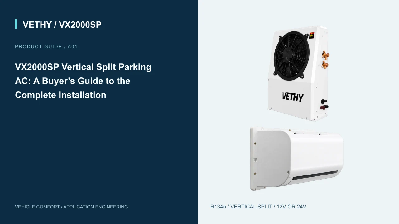
Buying a split parking air conditioner involves more than choosing a cooling figure. The finished result depends on where the outdoor unit fits, how indoor air moves through the cab, how the vehicle supplies electricity, and whether an installer can service the system later. These decisions work together: an attractive mounting position can become expensive if it forces an awkward pipe route or blocks routine vehicle maintenance.
The VETHY VX2000SP uses a vertical outdoor layout and a separate indoor unit. Its published specifications distinguish a 12V version rated at 2000W cooling and a 24V version rated at 2600W cooling. This guide turns those facts into a practical buying sequence, from the first vehicle measurements through installation acceptance. The two planning scenarios below are examples for organizing a project; they are not customer case studies or performance tests.
Keep the VX2000SP product page available during quotation discussions, and use the VX2000SP guide hub to connect installation decisions with power planning.
1. Decide what the complete installation must deliver
Begin with the parked activity you want to support. A driver waiting for loading has different priorities from a driver preparing a sleeping area. Record the expected occupancy, usual parking duration, frequency of door opening, location of the occupied space, and access to recharge between stops. These details help the supplier and installer assess the whole job without relying on a model name alone.
Write the desired outcome in everyday terms: cool the occupied cab during a defined waiting period, preserve an agreed battery reserve, and keep both units accessible for cleaning. Add any vehicle constraints, such as a frequently tilting cab, equipment already attached to the rear wall, or a location where loading personnel work close to the vehicle.
Then assign responsibility. The equipment supplier should identify the supplied components and required installation information. The installer should verify vehicle structure, routing, electrical protection, and workmanship. The buyer should supply accurate vehicle details and approve the intended operating routine. A short responsibility list makes omissions visible before they become costs.
A complete quotation should therefore describe equipment, mounting provisions, pipework, drainage, electrical work, commissioning, and handover. Ask for each item to be included, excluded, or priced separately. That is a more useful basis for comparison than a single delivered unit price.
2. Match the voltage version before comparing cooling capacity
VX2000SP specifications list two voltage versions. Choose the version around the confirmed supply architecture of the proposed installation. A truck being described as a particular vehicle class does not establish the available connection point or the condition of its electrical system.
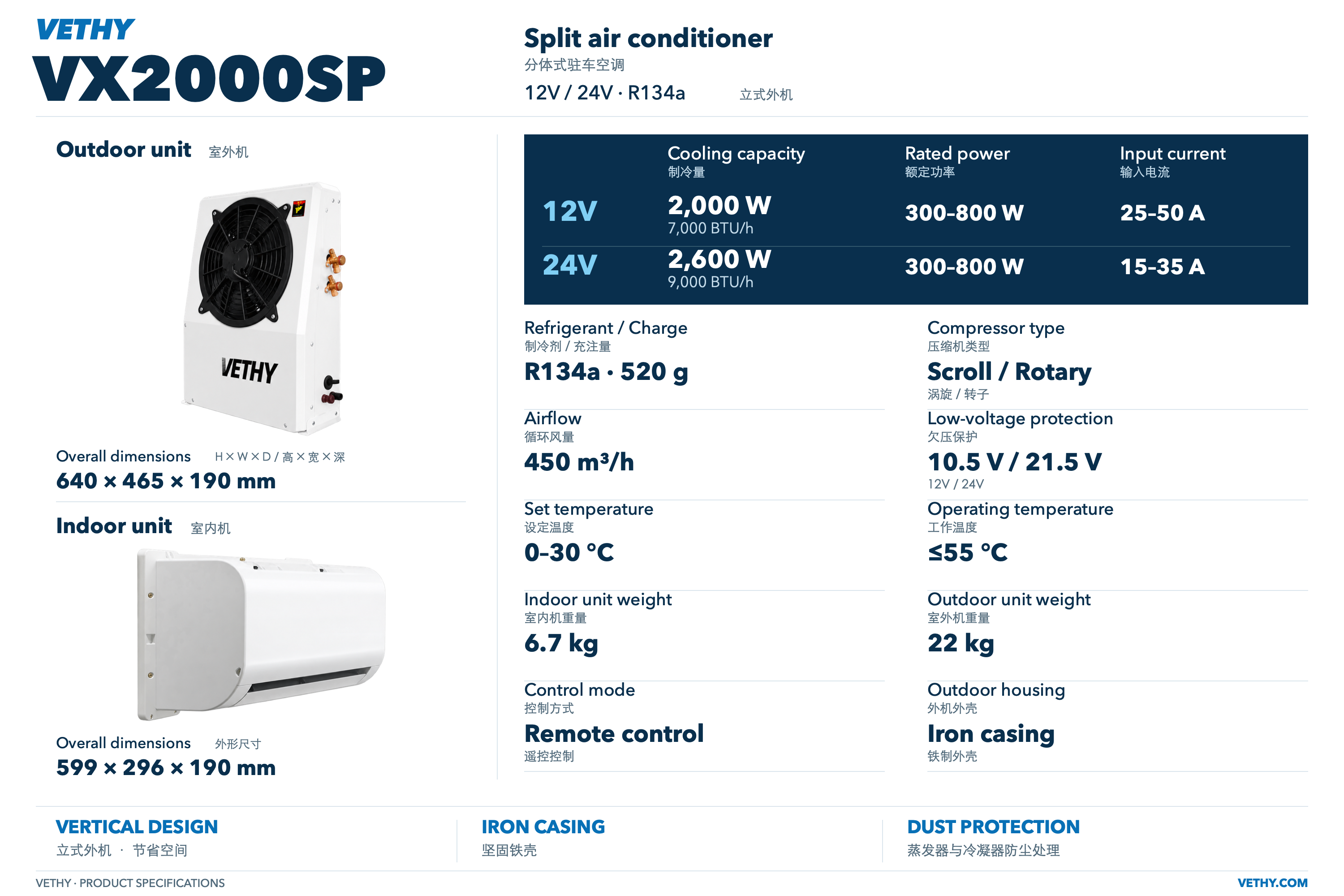
| Published reference | 12V version | 24V version |
|---|---|---|
| Cooling capacity | 2000W / 7000 BTU/h | 2600W / 9000 BTU/h |
| Rated power field | 300–800W | 300–800W |
| Input current field | 25–50A | 15–35A |
| Low voltage protection | 10.5V | 21.5V |
| Airflow | 450m³/h | 450m³/h |
These are separate published fields. They do not provide matched operating points from which to calculate efficiency, predict consumption during a particular stop, or size a cable by arithmetic alone. Request the installation requirements for the exact version being ordered.
Cooling capacity also needs context. The cab volume, glass area, insulation, parking exposure, and initial interior temperature all influence the cooling task. A larger published cooling figure does not remove the need to examine the proposed application. Give the supplier photographs and a clear description of the occupied area.
For a 12V project, continue with the cooling and recharge planning guide. Fleet buyers standardizing a 24V installation can use the 24V fleet specification guide.
3. Measure the outdoor location as a working envelope
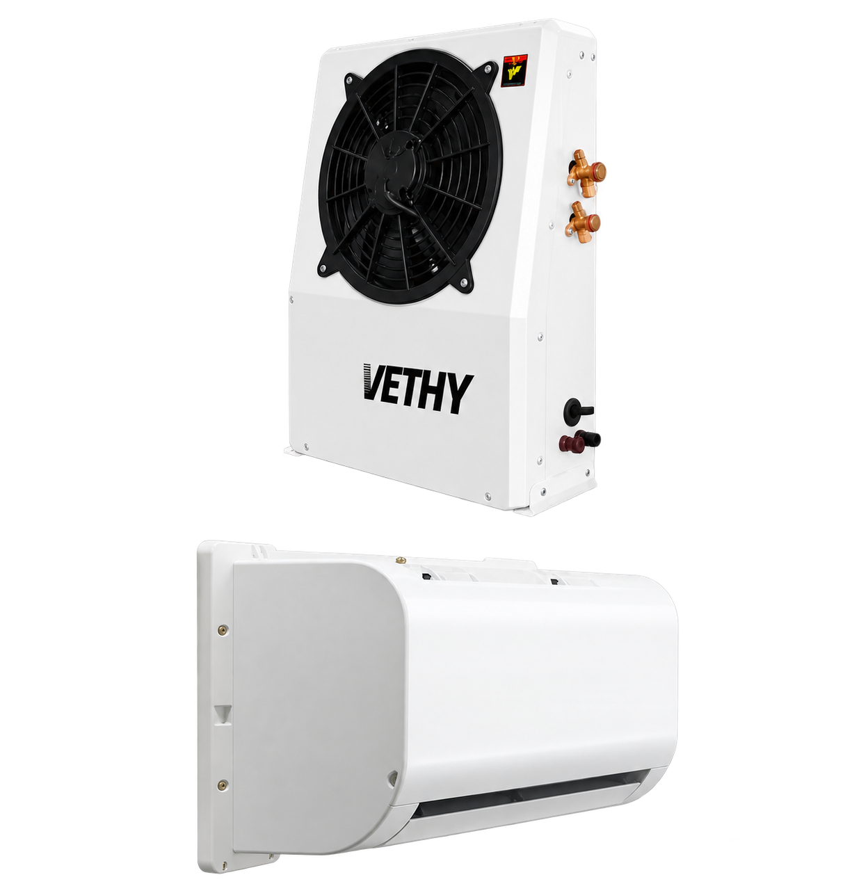
The outdoor unit is listed at 640mm high, 465mm wide, and 190mm deep. Start by making a cardboard outline or a simple drawing at those dimensions. Place it against the proposed vehicle location and photograph it from the rear, side, and service access direction. This immediately exposes conflicts that a close photograph of an empty panel can hide.
The unit dimensions describe the equipment body. The finished installation also needs space for brackets, pipe connections, cable entry, airflow, and service access. Obtain the required installation clearances from the supplier instead of treating the body outline as the final boundary.
Look at the vehicle in its operating states. A clear gap while parked may change when a cab tilts, a door swings, a trailer approaches, or equipment is moved. Check access to existing filters, locks, lights, inspection points, and vehicle labels. Include any covers or guards that the installer proposes.
Ask where a technician will stand to inspect the unit and how the unit could be removed later. If removal requires dismantling unrelated vehicle equipment, record that consequence before approving the location. A slightly different position may simplify years of maintenance.
The vertical arrangement is useful when the project calls for a tall outdoor footprint, but fit remains vehicle specific. Approve a dimensioned installation drawing with the actual vehicle identifier before fabrication begins.
4. Position the indoor unit around the occupied space
The published indoor dimensions are 599 × 296 × 190mm in the source order. Confirm the orientation of those dimensions against the supplied drawing before preparing a mounting surface. The source separately lists an indoor weight of 6.7kg; the weight basis should be confirmed when structural or handling calculations require it.
Positioning should begin with the person using the cab. Identify where the driver sits or rests, where return air can reach the unit, and what items are likely to obstruct discharge air. Bedding, curtains, storage bags, and aftermarket shelves can change the airflow path after installation even when the empty cab looks suitable.
The published airflow is 450m³/h. That figure helps identify the product, while a useful installed airflow path depends on the surrounding layout. Ask the installer to show the intended discharge and return routes on a cab photograph. Also confirm access for inspection and cleaning without requiring the driver to dismantle permanent trim.
Remote control is listed. During layout review, decide where the remote will be stored and whether the normal operating position gives convenient control access. Include cable and pipe exit positions in the drawing so that trim covers can be planned neatly. A clear indoor layout improves daily usability as well as the appearance of the finished installation.
5. Review brackets, structure, and access together
A mounting bracket transfers the equipment load into the vehicle. Its design therefore depends on the mounting surface and the loads expected in that vehicle installation. Ask the installer to identify attachment points, the proposed fastening method, and any reinforcement that will be required.
The source lists the outdoor weight as 22kg. It does not establish whether that figure is net, gross, or another weight basis. Keep it separate from the indoor figure and obtain the required weight information for the engineering assessment. Do not turn the two labels into a combined shipping or installed weight.
Review how the bracket affects adjacent systems. Fasteners should remain accessible, connections should have room to be inspected, and any vehicle movement should be accommodated in the approved design. The installer should also describe how openings and disturbed protective finishes will be treated for the actual location.
The outdoor housing is listed as iron casing. The material description is useful for identification, but the location still needs an appropriate protection and maintenance plan. Ask how the proposed installation will be inspected for coating damage and loose fittings.
Approve the mounting method together with the service access arrangement. Treating these as separate conversations can produce a strong bracket that makes ordinary maintenance unnecessarily difficult.
6. Plan the refrigerant, cable, and drain routes before drilling
Trace each route on vehicle photographs before work begins. Mark the indoor connection area, the path through the cab, the outdoor connection area, and every proposed penetration. A route review should reveal where components are protected, where connections can be reached, and where movement needs to be accommodated.
The VX2000SP sheet lists R134a refrigerant and a 520g refrigerant charge. The supplied configuration and installation procedure should explain how that charge relates to the delivered equipment and the approved installation. Ask for the required pipe lengths, connection procedure, and commissioning instructions rather than extending a route by assumption.
Plan condensate drainage as deliberately as refrigerant piping. Identify the intended discharge point and confirm that the installer can verify drainage under the vehicle's expected parked orientations. Keep water away from locations where it could wet stored items or interfere with access.
A neat installation should also remain understandable. Label connection points and retain a route drawing with the vehicle record. Where trim conceals a connection, record how the technician reaches it.
Before drilling, check both sides of each proposed opening and obtain approval for changes to the vehicle body. Agree how penetrations will be sealed and protected, then inspect them during handover while the installer is still available.
7. Give the electrical installer a defined operating plan
The electrical brief should identify the selected voltage version, battery arrangement, intended parking periods, other simultaneous loads, and available recharge sources. Supply this information early enough that electrical work can influence the mounting and routing plan.
The published power and current ranges are useful reference information, but the installer needs the exact equipment requirements and vehicle conditions to select conductors, protection, isolation, and connections. Route length and connection quality belong in that assessment. Ask for the installed connection points to be documented so that future work can be carried out consistently.
Low voltage protection is listed at 10.5V for the 12V version and 21.5V for the 24V version. These thresholds describe product protection references. The operating plan must separately define the battery reserve the buyer wants to preserve and how the driver will recognize it.
If several people use the vehicle, give them one clear routine for starting cooling, checking available energy, and ending a parking session. A driver should not need to interpret a technical specification table during a delivery stop.
Include electrical checks in installation acceptance. Record supply conditions under an agreed operating observation, inspect connections using the installer's procedure, and retain the electrical layout with the vehicle file. Those records become valuable when a later symptom needs to be separated from an equipment fault.
8. Read controls and environmental references in context
The published temperature setting range is 0–30°C. Choose an initial operating setting around the driver's comfort objective and the installation instructions. A control setting is a request to the system; it is not a promise that the cab will reach the selected number under every condition.
The sheet also lists an operating temperature reference of ≤55°C. This is a listed limit, not a cooling capacity test result at 55°C. Discuss the actual parking environment when evaluating suitability, especially when the outdoor location may be exposed to heat from nearby equipment or restricted air movement.
Dust protection treatment is listed for the evaporator and condenser. Turn that feature into a practical service conversation: which areas need inspection, how cleaning should be performed, and who will do it. The maintenance schedule should reflect actual operating conditions and the supplier's instructions.
The compressor line reads “Scroll / Rotary.” If the exact compressor arrangement matters to purchasing, servicing, or spare parts, obtain written confirmation for the ordered configuration. This wording alone does not define a particular compressor technology or control method.
Keep these questions together in a short technical clarification sheet. Resolving them once creates a reliable reference for purchasing, installation, and later support.
9. Planning scenario: a day cab with short loading waits
Consider an illustrative day cab used for several loading stops, with the driver staying inside for some of them. The buyer's first useful action is to record stop duration and occupied waiting time for a normal operating week. These observations help avoid designing the system around an unusually quiet or unusually difficult day.
For this scenario, suppose a rear mounting area appears available but a cab service panel occupies part of it. The installation review should compare two outdoor positions on a dimensioned drawing. One may provide a shorter pipe route, while the other preserves easier access to the service panel. The buyer can then compare the complete installation implications.
Inside the cab, photograph the actual storage arrangement with the driver's normal bags and equipment in place. Check that the proposed indoor location serves the seated position and remains accessible for cleaning. Confirm that the remote has a predictable storage location.
The electrical review should examine energy used over multiple stops and the opportunity to recharge between them. Define a simple driver observation record for the pilot period: stop start time, stop end time, initial conditions, chosen setting, and any interruption. The purpose is to establish a usable daily routine and reveal which assumptions need adjustment before another vehicle is fitted.
10. Planning scenario: a sleeper with competing rear equipment
Now consider an illustrative sleeper cab where the intended outdoor location is already shared with tool storage and other equipment. The buying decision begins with a space allocation drawing, not an order for brackets. Mark the VX2000SP body envelope, required clearances, access zones, and existing equipment movement.
Next, establish the occupied cooling area. A sleeper layout may involve curtains, shelves, and a berth positioned differently from the driving seat. Show those features in the indoor placement review. The buyer should be able to understand how air reaches the intended resting area and returns to the unit.
Longer parked use makes the energy plan particularly important. Record the desired cooling period, planned auxiliary loads, battery reserve objective, and next reliable recharge opportunity. Treat these as project inputs to be checked; the cooling capacity figure does not answer the runtime question.
For handover, ask the driver to operate the remote, identify routine inspection points, and describe what to do if cooling stops. Store the instructions in a location shared drivers can find. If the first installation will become a template for similar cabs, photograph the completed routes before covers are installed. This converts one carefully reviewed job into a repeatable installation package.
11. Request a quotation that can be compared line by line
Send one information pack to every bidder. Include vehicle details, electrical supply information, photographs, measured mounting space, intended use, and the responsibilities already agreed. Request the exact VX2000SP voltage version and the current specification sheet in the reply.
Ask the quotation to identify the supplied indoor and outdoor equipment, mounting hardware, connection materials, installation labor, commissioning work, and documentation. Where a component is optional, request its purpose and separate price. Where the installer needs to inspect the vehicle before giving a final price, record that dependency clearly.
Include a short acceptance list: approved mounting location, retained access to vehicle service points, documented routes, completed functional checks, and driver handover. Attach the same list to the purchase order. This keeps the final inspection connected to the original buying decision.
Before accepting delivery, reconcile the order description, carton labels, supplied components, and voltage identification. Keep photographs with the receipt record. Check the supplier's installation and support documents at the same time so that missing instructions can be resolved before the vehicle is taken out of service.
Finally, retain the completed installation record beside the product information. Future service becomes easier when the technician can see what was ordered, where it was fitted, and which checks were completed at handover.
12. Use handover to prove the installation is ready for work
Arrange handover while the installer can still open covers and explain the finished work. Walk through the approved drawing together, checking the outdoor location, indoor position, routes, penetrations, and service access. Record any departure from the drawing and decide whether it needs correction or an approved revision.
Ask the installer to demonstrate the required functional checks, including condensate drainage and the normal control sequence, using the supplier's instructions. Keep the observations and operating conditions in the commissioning record. Where an item cannot be completed during handover, identify the remaining action and its owner before closing the job.
Then let the driver demonstrate the daily routine. The driver should know where the remote is stored, how to begin and end an occupied cooling period, what energy indication to watch, and whom to contact with a problem. This short demonstration often reveals an instruction that needs clearer wording.
Finish by collecting the documents in one accessible place. A completed installation becomes easier to own when the equipment reference, approved layout, commissioning record, and operating instructions remain together after the installer leaves.
13. Frequently asked questions
Does VX2000SP fit every truck with a rear mounting area?
Fit depends on the vehicle, approved attachment points, required clearances, connections, and access. Start with the 640 × 465 × 190mm outdoor body dimensions, then add the supplier's installation requirements. A photograph of an empty panel is a useful first step, while a dimensioned layout is a stronger basis for approval. Include cab movement and nearby equipment in that layout.
Which voltage version should a buyer request?
Request the version matching the confirmed installation supply. Published cooling capacity is 2000W for 12V and 2600W for 24V, with separate listed power and current references. Have the installer verify the actual connection arrangement before ordering. Fleet buyers should identify the vehicle subgroup and approved electrical configuration in the purchase specification.
Can the lowest temperature setting be used as a cab temperature guarantee?
The 0–30°C range describes available settings. Actual cab conditions depend on the cooling task and installation environment. Define the comfort objective with the supplier and evaluate the installed result during an agreed observation. If the intended use involves refrigerated goods or temperature sensitive cargo, obtain equipment specifically assessed for that application.
What should be confirmed about the compressor?
The specification label is “Scroll / Rotary.” Ask the supplier to identify the exact compressor configuration supplied with the order when that detail affects procurement or spare parts. Keep that confirmation in the equipment record. Purchasing should use the confirmed configuration instead of adding assumptions to the model description.
What documents make the first installation easier to repeat?
Keep the approved layout, mounting detail, electrical arrangement, pipe and drain routes, supplied component list, commissioning record, and driver instructions. Photographs before covers are installed are especially useful. Together, these documents let a later installer understand both the visible finish and the concealed work, while preserving vehicle specific details for the next review.
Product sources
- VETHY VX2000SP verified product specifications — VETHY.
- VETHY VX2000SP bilingual specification sheet — VETHY.

VETHY product recommendation and application analysis. Specification references identify the selected model and voltage. Installation examples are planning examples; measured project results are identified explicitly when available.
Discuss your VX2000SP application
Send your vehicle, supply voltage, occupied space, parking schedule and installation photographs for a model-specific recommendation.
Prepare your vehicle brief ↗